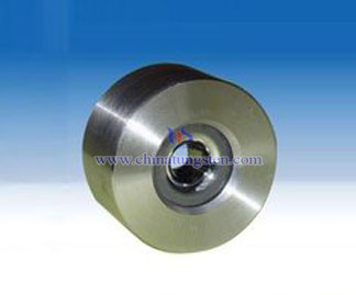
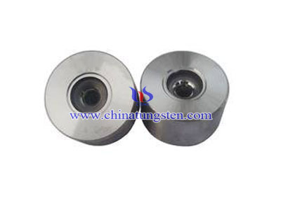
Tungsten Carbide Nibs for Metal Wires
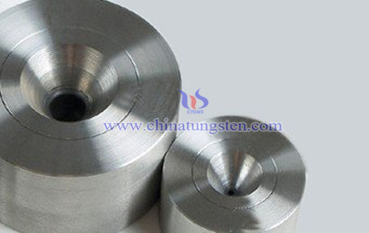
The art or process tungsten carbide nibs for metal wires like the name implies is to draw a wire of a bigger diameter through a hole with smaller diameter hereby reducing the diameter through plastic deformation while the volume remains the same.
In more technical terms it is an operation to produce wire of various sizes within certain specific tolerances. The process involves reducing the diameter of rods or wires by passing them through a series of tungsten carbide nibs with each successive die having smaller bore diameter than the one preceding it. The final wire size is reached as the wire passes through the last die in the series.
S01 Tungsten carbide nibs for drawing ferrous and nonferrous metal wires:
| Dimensions (mm) | Reference Dimenstions (mm) | |||||||
| D | H | d | 2α | 2γ | h | h1 | h2 | R |
| 6 | 4 | 0.2 | 40° | 60° | 0.8 | 0.6 | 0.8 | 1.5 |
| 8 | 6 | 0.2 | 40° | 60° | 1.0 | 0.6 | 1.0 | 2.5 |
S10 Tungsten carbide nibs for drawing ferrous and nonferrous metal wires:
| Dimensions (mm) | Reference Dimensions (mm) | |||||||
| D | H | d | 2α | 2γ | h | h1 | R | e |
| 6 | 4 | 0.4~0.8 | 40° | 60° | 0.8~1.2 | 0.8 | 1.0 | 0.5 |
| 8 | 6 | 0.4~0.8 | 1.0~1.5 | 1.5 | ||||
S11 Tungsten arbide nibs for drawing ferrous and nonferrous metal wires:
| Dimensions (mm) | Reference Dimensions(mm) | |||||||
| D | H | d | 2α | 2γ | h | h1 | R | e |
| 8 | 6 | 0.4~1.2 | 12°~16° | 60° | 0.3~0.6 | 1.0 | 2.0 | 0.5 |
| 12 | 10 | 0.4~2.3 | 14°~16° | 90° | 0.4~1.2 | 1.2 | 3.5~4.0 | 1.0 |
| 13 | 10 | 0.4~2.6 | 12°~18° | 60° 90° | 0.3~1.4 | 1.2~1.5 | 2.0~4.0 | 1.0 |
| 15 | 13 | 0.4~2.8 | 14°~16° | 90° | 0.4~1.5 | 1.5 | 7.0~9.1 | 1.2 |
| 16 | 13 | 0.4~3.2 | 16° | 60° | 0.2~1.3 | 1.5 | 5.0 | 1.0 |
| 16 | 14 | 0.4~2.8 | 18° | 60° | 0.3~1.4 | 1.5 | 4.0 | 1.0 |
| 19 | 16 | 2.3~5.9 | 16°~18° | 75° | 1.2~2.0 | 2.5 | 7.9~9.6 | 1.5 |
| 20 | 17 | 2.3~6.0 | 16°~18° | 60° 75° | 2.3~2.6 | 2.5 | 5.0~9.8 | 1.2 |
| 21 | 17 | 1.6~5.7 | 18° | 60° | 1.2~3.0 | 2.5 | 5.0 | 1.2 |
| 22 | 18 | 1.5~6.3 | 18° | 60° | 1.2~2.6 | 2.5 | 5.0~8.0 | 1.2 |

